Sputnik
On October 4th 1957
the Russians launched the Sputnik
satellite, (also spelled satelite). It
was little more
than a radio
transmitter in a metal sphere but it's launch into orbit from a
propaganda point of view, was used to taut the superiority
of the Communist political system over Capitolism. The Soviet
Union took the lead in the new race for space. This event and
news of it came as a great shock to the western
world at the
time.
// 1957 Sputnik
Though the
Americans were the first to develop the nuclear
bomb, the Russians soon had it too. The real possibility of
nuclear
bombs being delivered via intercontinental missiles
brought tensions to new heights between communist and
capitalist blocks. This period marked the height of what
was called 'the Cold War'.
DARPA
President
Eisenhower, who earlier had been the military
leader of American and allied military forces up to the end
of the
Second World War, responded to the Sputnik launch
with different
initiatives,
one
which was ARPA, or, the
Advanced Research
Project
Agency.
ARPA was started
under the auspices of the the Department
of
Defence.
ARPA became better known
as DARPA and
sponsored many research projects at various universities.
At that time computer networks
and the Internet didn't exist.
// The 'Day of the Jackal' was an
interesting movie in that it depicted
// the state of
'intelligence
gathering' before the advent of computers.
// The
main connectivity
was supplied by telephones.
'Data banks' were
// large
multi-leveled rooms where
paper files were stored on
shelves
// like libraries. Other than
the phone,
information was delivered by post,
// courier or 'the wire'.
'The Galactic Network', An Early Vision of the Internet
In 1962 J.
Licklider, soon after being appointed the head
of research
at DARPA
wrote a series of memos describing
a "Galactic Network", a vision of
a global
network of
computers which could be accessed as a single collective
from any one
site. Licklider passed the concept on to his
successors at DARPA, Ivan
Sutherland,
Bob Taylor, and
MIT researcher Lawrence G. Roberts.
//
1962 Galactic Network, 1962 to put the date in perspective is
about
// the time the Beatles debuted
Packet Theory
MIT researcher
Leonard Kleinrock in 1961 published the first
paper on
packet
switching theory. Kleinrock made the case
that 'packets' of information rather than strict circuit connections
could be used as a basis for communications. ( The idea
was
to group sets
of discrete signals into packets which would
traverse wire.) In 1964 he wrote a book
to further
support his
theory.
//
1961-1964
Packet
Theory short discrete bursts of information
Parallel Tracks
Meanwhile, Paul
Baran and others at the secretive RAND
corporation had written a paper on packet
switching
networks
for secure voice communication for the military in 1964. At
around the same
time Donald Davies and Roger Scantlebury
of
the British National Physics Laboratory
had also written
a paper on a packet network concept from the UK.
Apparently
all
three groups were developing the packet-based
systems
of communication, independently.
From the time lines
described here, it seems Kleinrock has the earliest
paper
published
on the topic. (The word "packet" was apparently
adopted from his work
at NPL.)
//
Rand & British National Physics Laboratory on same track
The First WAN
In 1965, together
with Thomas Merrill, Lawrence Roberts
connected a computer in
Massachusetts
to another in
California with a low speed dial-up telephone line creating
the first Wide-Area Network or WAN. In 1966 Roberts
proposed to DARPA a plan to build
a computer
network
called the ARPANET. His proposal was published in
1967.
//
this link talks about Roberts and many other Internet pioneers
http://www.livinginternet.com/i/ii_roberts.htm // click 'UP'
//
1965 first network link California to Massachusetts
Kleinrock's Center
at UCLA was the first ARPANET node
and connected to a second node supervised by Doug
Engelbart at the Stanford
Research
Institute.
The SRI supported
the Network Information Center, ( NIC, )
led by Elizabeth
Feinler which maintained tables of host
name to address network mapping. Also maintained by NIC
was a directory of 'RFCs' or Recommendations for
Consideration.
Two more nodes were
added, UC Santa Barbara (managed
by G.
Culler
and B. Fried) and the University of Utah under the
supervision
of Robert Taylor
and Ivan Sutherland. By the end
of 1969 there were 4 nodes on the
ARPANET.
1969 Four Node Internet With
Names of Mainframes
// info
adapted from an early sketch ref. below
#2
SRI
(940) ____ #4 Utah (PDP 10)
/ |
#3 UCSB(360) |
\ |
#1 UCLA (Sigma 10)
# 1 University of California Los Angelos
# 2 Stanford Reseach Center
# 3 University of California Santa Barbara
# 4 University of Utah
//
Robert Taylor and Ivan Sutherland were also actively
// investigating how to
represent
3-D objects
Network Control Protocol
Computers
were
added
to the network at a quick rate after
this time. In 1970, S. Crocker
led a group
that finished the
first Host-to-Host protocol for the ARPANET, called the
Network
Control
Protocol, or NCP.
// 1970 NCP, first host-to-host protocol
// Nice related info and includesa scrawled diagram describing the
four
// first nodes of the internet
http://www.sharpnet.co.uk/winter.shtml
E-Mail
// 1972 E-Mail was introduced
TCP/IP
Robert Kahn
developed an architecture for communications
over networks to
take place at
the operating system level. The
design he envisioned proposed that networks were
autonomous
units and not dependent on the 'Inter-network' to continue
functioning. He
chose a packet transmission policy where
packets that didn't reach
their target would be
re-transmitted.
//
protocol retransmitted packets that didn't reach target
The
Internetwork // precursor
of the term, Internet
He envisioned the
different networks being connected
by
'black boxes',
what would become 'gateways' and 'routers'.
These boxes would pass packets
but not
retain any information
so they would remain simple and able to quickly recover from
failure. Also, Kahn included the idea that there would be no
'global' or centralized
control of the
'Internetwork's' operations.
//
stateless interconnectors with no centralized control
Kahn teamed up with
the operating system expert, Vinton
Cerf (also known as 'Vint' Cerf) to create a practical blueprint
for the
communication
scheme. At a conference at Sussex
University in September of 1973, they spelled
out what was
effectively the first specification for the TCP protocol.
//
1973 TCP protocol spelled out by Kahn & Cerf
The original
paper had only
described the TCP protocol. It
would be able to provide a
reliable
service
where all packet
deliveries were acknowledged, and a second 'unreliable
datagram
model' or 'UDP'
where an occasional loss of a
packet could be tolerated.
In the end, TCP was
implemented with only the 'virtual
circuit' model,
where packet
delivery was acknowledged.
This led to reorganizing the model into
three parts. The
TCP protocol handled flow control and lost packet
recovery. The IP
protocol would
deal addressing machines
and seeing that packets arrived at their
destinations.
The
UDP or User Datagram Protocol would provide a
broadcast delivery
service
where
packet loss was ignored.
Transmission Control
Protocol was first used in 1977.
TCP Components
// TCP
was first used in 1977
Berkeley Sockets
DARPA supported efforts at UC Berkeley to
investigate
adapting TCP/IP
to the Unix environment. Berkeley
researchers
rewrote the code for TCP/IP so it would
work
efficiently with Unix. ( By 1984 Berkeley
Unix was released
as version 4.2
BSD. The TCP/IP support found in BSD
4.2 would soon become the
de facto standard for the
Internet.)
//
1984 BSD 4.2, Berkeley Unix 'sockets' became Internet standard
The socket model developed at Berkely for
inter-process
and network communication,
popularly known as 'Berkeley
sockets', became
widely adopted in other operating
systems
such as those of Microsoft and Apple.
The incorporation of
TCP/IP in BSD
Unix helped to popularize
the TCP/IP
protocol with
researchers at various academic
institutions.
ARPANET Switches
from NCP to TCP/IP in 1983
In 1983, ARPANet switched from NCP, Network Control
Protocol to TCP/IP. This was a recognition
of
TCP/IP's
increasing dominance as
the primary communication
protocol of the Internet. By this time the
original
ARPNet
was just one of many
interconnected networks.
//
1983 ARPANet switches from NCP to TCP/IP
The
Beginning of IP
addresses
Originally, it was
felt there would only be a small number of
national
level networks.
A 32-bit address scheme was devised
where the first 8 bits would be used
to describe
the networks.
FTP or 'File
Transfer Protocol' replaced paper and conventional
mail as the preferred way of
communicating
RFCs. Today, RFCs
are widely available in the form of HTML pages on the World
Wide
Web.
Over
time these informal communications became a forum for
the release of formal technical documents, official standards
and specifications. Today, the RFCs also serve as interesting
historical documentation of technical aspects of the Internet.
Web Applications
Today SMTP E-mail,
FTP file
transfer, HTML-based web
surfing are the most famous of
web applications.
In the early
days of computing Telnet was also important. In these
days, the
mainframe
computers at the hearts of the various institiutions
that were
connected
to the early
ARPANET, were extremely
expensive. TELNET was a program that supplied a
remote
terminal to a mainframe and served as primary means of
sharing
access to the
valuable, mainframe computer resource.
The World Wide Web
Tim Berners-Lee, working at CERN in Geneva
in 1990
co-authored with R. Fielding
and H. Frystyk the RFC entitled
the HyperText
Tranfer Protocol. This along with the
invention
of HTML by the same researchers, led
to the creation of the
World Wide
Web which revolutionized the Internet into the
'Net'
we are familiar with today with
it's many browsers and plethora
of images and hyperlinks.
// 1990 -> HTTP and the World Wide Web
While the hyperlinked Internet of the
90's remains in place, the
net is increasingly becoming an audio video domain which is
posed to absorb traditional audio and video broadcasting.
A protocol is a set of rules for
communcation. Today's networks
are divided into different communication layers. Depending on
the layer, protocols exchange electrical signals, data packets,
characters, words or tokens in
predefined
formats enable two
machines to engage in communication.
// a
protocol is a set of rules for communication
Protocols
are used to specify how data is
placed in packets
and
how these packets are to be read when received at communication
end points.
Protocols work at
different layers of the Internet. For instance at
the
'data link' layer, the Ethernet or Token Ring protocols
might
be
used. At the 'network' layer the IP protocol is
used. At the
transport layer the TCP protocol is used.
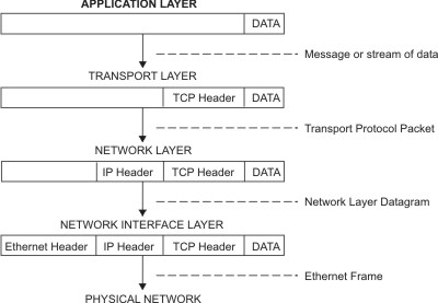
Each protocol
makes use of specially tailored
packets
that will
carry information in a particular ordered sequence. As
data
is
passed
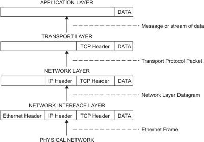
between the different layers of the network, packets are
nested or
removed to reveal
the information pertinent to that layer.
//
Packets are nested, low-level packets act as carriers of high level packets.
In network
communcation, packets or frames will typically include
addressing
information, protocol control information, bytes or
symbols that
delineate
the start
and end of packets, the message
data and an error test to see if the
data was
received correctly.
The packet design is the essential
blueprint that allows
a protocol
to work.
TCP
Packet
As an example, a
TCP
packet contains 11 fixed-length fields and
one variable
field
that carries user data. Each of the first eleven fields
of the header
contain
values that
the protocol uses to operate. A
sender and the receiver agree to
exchange data according to a set
of rules which is the protocol.
The following
diagram shows how information is sequenced inside
a TCP packet.
Breakdown of a TCP packet
Source
ID
field names
|
Destination
ID
|
|
Sequence
number
|
|
|
ACK number
|
|
|
|
Header length
|
|
|
|
|
Unused
|
|
|
|
|
| Flags
|
|
|
|
|
|
|Flow control
|
|
|
|
|
|
| |
CRC 16
|
|
|
|
|
|
| | | Urgent Pointer
|
|
|
|
|
|
| | |
| Option
|
|
|
|
|
|
| | |
| | User Data
|
|
|
|
|
|
| | |
| | |
|||||||||||||||||||||||||||||||||||||||||||||||||||||||||||||||||||||||||||||.
.
.
16
16
32
32 4 6
6 16 16
16 16 variable
number of bits per field
The
IP protocol
has it's own packet that is responsible for addressing
and routing
a packet through
the network. The TCP packet nests inside
the IP protocol packet.
Frame vs. Packets
There is a bit of
ambiguity about what defines a frame and a packet.
In general it would
seem that the frame and the
packet are often used
interchangeably although the frame may be thought of the larger carrier
of packets.
Layers
of
the
TCP/IP Model
Network operations have been divided into different communications
layers. Different
models use different numbers of layers, either four,
five
and seven layers.
The TCP/IP model uses five
layers and predates the publication
of the
seven layer OSI model standardized by the
International Standards
Organization,
ISO. ( OSI abbreviates Open Systems
Interconnection. )
The
seven layer OSI model
is useful because it allows many different
network
protocols
used by different operating systems to be mapped
against it.
Since Java builds TCP/IP sockets exclusively and TCP/IP is the
dominant protocol used today
our focus may be placed on the five
layer TCP/IP model. The following
diagram shows the different layers
of
the TCP/IP model.
Diagram
of
the
5 Layers of the TCP/IP Model
| Application |
| Transport / TCP / UDP |
| Network / IP layer |
| DataLink |
| Physical |
// The
top three layers of the OSI model are a further division
// of the one application layer defined in the TCP/IP model
Following are details of each of the five layers described in
the TCP/IP system.
The Physical layer // electric, optic or radio signals
The physical layer
is also referred to as Layer 1. Layer 1
takes care of the transmission
and reception of data over
the network cable, satellite or other
connection
medium.
The physical layer includes the input and output
aspects
of the the network interface
card or NIC that connects to
network circuitry.
This layer deals with the transmission
of light pulses through fiber-optic cable, the
transmission
of radio wave signals to
satellites and receiving dishes
and the
transmission
of electric signals over copper
wire.
The Data Link Layer // ethernet packets, NICs
The DataLink Layer is also called Layer 2. At
Layer 2,
data from higher levels is
placed in 'data link layer'
packets and sent
across the connection
medium.
Today these packets are most
typically Ethernet units.
The Data Link Layer manages it's own
error checking
to
ensure that data is correctly sent and received. The
data link layer
also governs
how the circuits of the
physical layer are accessed. The activities
of the
DataLink
layer are associated physically with the
operation of the Network Interface
card.
Internet Protocol Layer // addressing
The IP Layer is also known as Layer 3. This layer
is
normally implemented in the software
that is referred to
as the TCP/IP stack or suite. This layer
is responsible
for providing addressing
information so that machines
can be addressed
over the network. It also works with
packets in transit assisting the routing process.
The IP
protocol includes error checking in it's header.
When this layer receives data from the
layer below it
checks the header to
determine
if it is the intended
recipient of that data.
In reverse, the IP layer adds a
header containing a destination address
to a data packet
and passes it down to the data link layer for transmission
over the physical transmission layer.
Java doesn't reach
down as far as to supply control of IP
level functions like network system configuration and routing.
The Transmission
Control Protocol
// port & sequencing #s, redundancy checking, acknowledgement
TCP works at Layer
4. The TCP protocol adds a second
header containing
a 'port'
number to the datagram and a
sequence
number (before passing them down to the IP
layer) In reverse, the TCP layer 'inspects' datagrams that
are passed up from
the IP layer to
determine the port
destination. Additionally, a
TCP data block will carry a
cyclic
redundancy check number that can be checked
to
confirm data has not been corrupted.
The port number is used to identify the type
of application
that is being addressed. FTP for instance
uses
the port
number '21'.
// port number identifies the associated application
The sequence number
allows a set of packets to be
reassembled 'in order'. This allows items that have been
segmented for transit to be reconstituted. This is neccessary
as the
application
layer may
pass large blocks of data that
may ultimately arrive in large numbers of small packets out
of order.
The redundancy
check
provides a means to confirm
that the data received has all been sent correctly.
The TCP protocol
also has an
'acknowledgement' field.
If correctly transmitted, the protocol
requires
the recipient
to
send an acknowledgement of receipt back to the
sender. If the
acknowledgement
doesn't come back in
a reasonable length of time, the sender will
retransmit
the data.
Frequent failures will result in abandoning the
attempt to send the
data.
//
CRC or cyclic redundancy check confirms data is correct
//
the
'ACK'
is sent by the receiver to acknowledge receipt of packets
User Datagram Protocol
User or Datagram Protocol also works at Layer
4. UDP
has no acknowledgement
mechanism so hasn't the
ability to inform
a sender of failure in communications.
This
is where it gets it's not so complimentary 'nickname',
"Unreliable Data Protocol'. UDP has less
'overhead' than
TCP so is used in for streaming of media data where
an occasionally loss of data is not that critical. UDP
is the broadcast
version of the TCP
protocol.
The Application Layer
The top layer is
the application layer and is 'Layer 5' in
the TCP/IP
Layer model.
This is the layer that browsers
and web servers use as well as e-mail and FTP programs.
The OSI model goes
on to further sub-classify this layer to
include
a session layer
which establishes and coordinates
connections
between two computers, a
presentation layer,
where files get converted
from one format to another,
( ie.this
might be the case in communications between
computers
using differing operating
systems or file
systems), and the application
layer where high level
protocols are
communicated from within applications.
TCP Application Layer Maps To -->
OSI --> Session, Presentation , and Application layer
Following shows a
diagram of how the headers are
of each protocol layer are added to create the frame
that travels over the Internet.
TCP/IP Packet Nesting //
diagram from the IBM web site
Application to Net Packeting
Net to Application 'Depacketing'
// from
http://publib.boulder.ibm.com/infocenter/pseries/v5r3/index.jsp?topic=/com.ibm.aix.commadmn/doc/commadmndita/tcpip_protocols.htm
Classic 4 Byte Addressing
On a TCP/IP network, each machine is assigned
an IP address,
a
32-bit number
that uniquely addresses a computer. TCP/IP
addresses
uses a 'dotted decimal' format
representing four
underlying 8-digit binary numbers. In decimal there are up to
three numbers called 'octets'. ( They are
called octets because
they each represent a byte or 8 bits of information.)
IP Address Example
195.222.55.33
// format: 'xxx.xxx.xxx.xxx'
// where 'xxx' is a decimal
number 0 to 255
While an 8-digit binary number is a byte with a range 0
to 255,
with IP
addresses, the numbers used are
normally 1 to 254 with
the values, 0 and 255 being reserved for special functions.
The Subnet Mask
This IP address may
be logically ANDED with a another 'dotted
octet' called the Subnet Mask. The Subnet
Mask
is
used to
separate out the net
part of an IP address.
IP Submask
Example
255.255.255.0
The 255 is in
binary 11111111, which when ANDED with the IP
Address
separates
out the network portion. The subnet mask,
255.0.0.0 isolates a class
A network.
The mask 255.255.0.0
isolates a class B network and 255.255.255.0
masks for a type
C network. There are class D and E networks but they
are not
available for network use.
Example of Mask Use
IPv6
To address the
imminent shortage of internet addresses the new
IPv6
standard
is being implemented, which uses 16 byte
addresses
which will yield a possible
3.2 x 10 38 addresses.
What is the Informal Status of IPV6
A quick 'google'
shows that while in 2009, IPV6 traffic represented
less than 1% of Internet traffic it is expected that IPV4 addresses
will be exausted sometime in 2012, so the push will soon be on.
In the early days
of networks, no one anticipated that the Internet
would grow so
large! The initial way network addresses were
issued was not very
efficient.
Network classes were based on
subdivisions of IP addresses.
The following table shows how networks were initially divided and
issued.
Table of Network
Classes
| Network Class |
Available Addresses |
Structure . |
1st Byte
Range |
Example . |
# Nets possible |
Percent Assigned |
| Class A | ~ 16 M | first byte fixed | 1-126 | 55.x.x.x | 126 | 100% |
| Class B | ~ 65 K | first two bytes fixed |
128-191 | 144.89.x.x | ~16K | 80% |
| Class C | 254 | first three bytes fixed |
192-223 | 200.3.3.2 | ~2M | 30% |
| Class D | ~200 M | 4 bytes--- | 240-247 | used for multicast |
------ | ----- |
| Class E | reserved | experimental | purposes |
//
223 to 240? military etc.
Classless Internetwork Domain Routing ( CIDR )
Since then, the
Internet governing body has been reclaiming
network
addresses
and using a scheme called CIDR, (briefly
described below) .This system
is
more granular and can include
a varying number of possible machine
addresses.
This system has delayed but will not prevent a migration to IPv6.
Because of the shortage of IP addresses and because
the
number of addresses issued
with class B or C networks is
inflexible (too little or too many), the InterNIC
has created CIDR
network types which have a
varied
number of addresses. They
are
described as slash 0 to slash 32. slash 0 which
is a hypothetical
net that isn't available
and has about 4 billion possible addresses.
Slash
32 has a single address, also not
practical as you need at
least the network, the
broadcast and a single node address.
Slash 30 has 4 addresses and the Slashes multiply
by two as
you go up. (i.e slash 29
has 8 addresses, slash 28 has 16
addresses etc.)
Subnets
Each organization must assign the addresses it
has received to
the computers on it's
network. Addresses are normally assigned
so all
the computers on one local area
network have similar
addresses. For instance
a college class C network might have
the Computer Science Dept. at 133.9.2.x while the
Business
school might be on 133.9.3.x
and so on. Each of these LANs
would be called
a TCP/IP subnet.
The Domain Name Service
To make them more comprehensible, IP addresses
have been
given name aliases.
This job is done by the DNS an abbreviation
of
Domain Name Service. This is a
global distributed database.
Each organization
on the Internet maintains it's list of
machine
addresses and domain names and makes
them accessible to
the collective.
Routers
&
Gateways
Some machines in a sub-network have two IP
addresses,
one
locating it on it's own
network, along with a second IP address
locating
it on another sub-network as well.
This machine is then
able to 'route' or
act as a 'gateway'
that connects machines
that
are on either of the two networks. All the
sub-networks
of the
Internet are interconnected
in this fashion allowing all the machine
of the
Internet to communicate with each other.
// today dedicated
computers such as routers and switches
// handle inter-network communications
The following table shows domain names that were
adopted
early
on. To help cover
an expected shortage in names, the International
Ad Hoc Committee, proposed seven
additional suffixes in addition
to the six
already
in use. Congestion will also be further
alleviated
by the addition of more names that
will be available for Internet use.
The Original Internet Domain Name
Suffixes
| Ending | Application |
| .arts | cultural groups |
| .com | business & individuals |
| .edu | schools |
| .firm | business |
| .gov | government |
| .info | information services |
| .mil | military |
| .net | ISPs |
| .org | groups & organizations |
| .nom | individuals |
| .rec | recreational sites |
| .store | retailers |
| .web | web organizations |
From Java IO to Networking
Java Networking takes IO one step further, allowing streaming
between sockets on different machines. To review, following is
a short IO example. In passing it shows the getEncoding( )
method of InputStreamReader class. While the example below
doesn't use read( ) and write( ) methods we will see the IO
classes combine with the java.net classes to create Java client
and servers.
Example Showing An Encoding Used in a Text File
// File created using Linux & 'kwrite'
editor
import java.io.*;
class Encode{
public static void main(String[]args)throws FileNotFoundException{
FileInputStream fis = new FileInputStream("Zee.txt");
InputStreamReader isr=new InputStreamReader(fis);
String encoding = isr.getEncoding( );
System.out.println("Encoding: " + encoding);
}
}
OUTPUT
Encoding: ISO8859_1
// Windows XP
Using Notepad the Output is: Encoding: Cp1252
While Networking
is a big topic on it's own, Java reduces it's
coverage to what needs to be known. Java sockets are as
easy to use as telephone numbers. (Well not quite!).
We don't need to
understand
the telephone
system in order
to use a phone. Similarly, Java allows the programmer to
open sockets on IP
addresses and port numbers and that
is all that is needed to make
a connection.
Where Java students
do not escape understanding the
complexities of networking is in surveying the various
classes of the Java API that act as wrappers for many of
functionalities that the network provides.
For now
we focus on
the classic client and server, built using
Java sockets. In the next
section we will look
at more classes
of the java.net package.
Generic Client and Server // Servers are listening
A 'client' is a piece of software which is able
to open a data
stream on another piece of software
called a 'server'. What
distinguishes the two is the server
is normally always running,
'listening' or
waiting
to be contacted by a client while
the client
is started as required and initiates
the connection with the server.
(An
alternate arrangement can exist where the server
may be
activated by a client's request
for a connection.)
In Java client-server relationships,
both classes will have
socket objects
which may be used to connect the two
pieces of
software remotely through a network connection.
// a client initiates communications with
the server
// which is expected to be listening
for connections
ServerSocket &
Socket Classes
In Java, a server
uses an instance of the ServerSocket
class
to 'listen for' and
'accept' requests for connections from clients.
The client uses a Socket class
instance to connect to the server.
Because the client and server are
normally run
from their own
dedicated machines we often think
of each being the machine
itself. This notion is strengthened by
the fact that we think of our
machines have been assigned Internet addresses and port
numbers.
localhost
A client and server
can both be run in separate processes on
the same
machine. In other words a server can be opened in
one DOS session and a client in another DOS window. They
may communicate via a special IP address known as 'localhost',
where the local machine is serving as a host for both server
and client.
As a matter of
historical fact, communicating processes on a
mainframe were first connected 'locally'. Remote connections
via sockets evolved from these early
efforts to allow
processes
running on the same mainframe
computer to
communicate with
each other.
Being able to run both client and server on the same
machine is
very convenient for the Java programmer, allowing easy testing
and development of client-server architectures in advance of
deploying the resultant applications over local networks or the
Internet.
To run a client and a server
locally,
the string literal "localhost"
is
used as the domain name. The equivalent is
the specially assigned,
four byte value,
network address, 127.0.0.1 used to represent the
same 'localhost' address. Sometimes you may see or hear the
'localhost' address being referred to as the 'loopback'
address.
Local Host Domain Name and Network Address
Connecting
When the client instantiates it's socket, an attempt
is made to
make a connection to the server that is specified by an IP
address provided as an
argument
to the
Socket constructor,
(host and port
number). The server socket in response doesn't
itself engage
in a connection to the client. Instead,
the server
spawns a new Socket object as a return
value from it's accept( )
method.
( It isn't explicit but behind the scene another
'synchronized'
version of accept( ) is
in-lined in this process.)
// synchonization makes processing
consistent in a
multi-threaded environment.
This new Socket
is assigned a port number which is shared
with the client. The new socket is opened on
the client's IP
address and port number
and the Client Server connection is
complete.
Both programs can then create low-level, input/output
streams using
the Socket class'
getInputStream( )and getOutputStream( ) methods.
Once these streams are in place
reading and writing can begin
between
the connected parties.
Essential Elements of a Client
After making the java.net package available by
importing;
1) Creation of a Socket object
Example
Socket socket=new Socket("localhost", 7799);
// 1. new Socket on localhost,
port 7799
2) Open streams (optionally adding specialized
secondary
streams)
Streams are opened in both directions with Java's
implementation of a Socket.
Example
InputStream
is = socket.getInputStream( );
OutputStream os = socket.getOutputStream( );
//2.a open streams via provided methods
DataOutputStream dos = new DataOutputStream(os);
DataInputStream dis = new DataInputStream(is);
// 2.b. higher -level
streams may be added to provide
// additional methods
3) Call read( ) & writes( ) on stream instances
to the
protocol's specialization.
Like with standard java.io package streams once you
have
references for the streams
you read and write to them
whatever it is you
wish to communicate.
Example
dos.writeUTF(toSend);
String back= dis.readUTF( );
System.out.println(back);
// 3. do read and writes
4) Close streams with close( )
Example
dos.flush( );
dos.close( );
dis.close( );
os.close( );
is.close( );
// 4. closing streams
From a practical view, the methods of the
networking classes
will be susceptible to failed connections, whether to down or non-
existent servers or breaks in connection. The java.net package
has a number of it's own exceptions that show up in code samples
of classes from that package. Frequently, though because IO
stream class methods are used, the exception handling involves
catching IOException.
Following is a complete client example. Notice
the new
import of the net
package.
Client
Code
Sample
// import the java.net
// and java.io packages
import java.io.*;
import java.net.*;
class Client{
public static
void main(String[]args){
String toSend;
toSend="Default";
if (args.length<1){
System.out.println
("Restart providing a word argument at the command
line");
System.exit(0);
}
toSend=args[0];
try{
// 1.
new
Socket on localhost, port 7799
Socket socket=new Socket("localhost",
7799);
//2.a.
open streams via factory methods
InputStream is = socket.getInputStream(
);
OutputStream os =
socket.getOutputStream(
);
// b.
layered
higher level streams
DataOutputStream dos = new
DataOutputStream(os);
DataInputStream dis = new
DataInputStream(is);
// 3. do read and writes
dos.writeUTF(toSend);
//
note the client writes into 'thin air', actually
// out through the socket to
the server. The
// client then reads back the
server's response
String back= dis.readUTF(
);
Sstem.out.println(back);
// 4. close streams
dos.flush(
);
dos.close( );
dis.close( );
os.close( );
is.close( );
}
catch(IOException
io){System.out.println("IO
exception");}
}
}
Essential Elements of a Server
1) Creation of a ServerSocket object.
The server uses it's own ServerSocket class object. In
the
process of making a connection, this object spawns a regular
Socket object for each client from which it
receives a
request.
Example
ServerSocket ss=new ServerSocket(7799);
2) A listening loop containing the accept( ) method. The
following for loop form is sometimes called a 'forever loop'.
Example
for(
; ; ){
// . . .
Socket socket = ss.accept( );
// . . .
}
//
2. characteristic listening loop
3) Open stream(s), optionally adding buffered
and specialized
secondary streams
Example
InputStream
is=socket.getInputStream();
DataInputStream dis=new DataInputStream(is);
// 3. open
streams
4) call read( ) & writes( ) on stream instances.
Example
s =dis.readUTF( );
String uppercase =
s.toUpperCase( );
dos.writeUTF(uppercase);
// 4. read & writes
5) close( ) streams
Example
dos.flush(
);
dos.close( );
dis.close( );
is.close( );
os.close( );
// 5. close streams
A Java Server
Following are
examples of a simple server. The client uses
a Socket
class
object while the Server uses a ServerSocket
class object. In an
unending
loop the ServerSocket's accept( )
method spawns a regular Socket object
which completes the
connection to the client. Steams are obtained on
these
socket
objects that permit reading and writing to take place between
the
client and server.
Server Code Sample
import
java.io.*;
import
java.net.*;
class
Server{
static
int
hits;
// default initialization is zero
public
static
void
main(String[]args){
ServerSocket
ss;
try{
System.out.println("Press
Ctrl-C
to
exit server");
ss=new
ServerSocket(7799);
// 1. new ServerSocket
for(;;){
// 2. 'forever'
loop
System.out.println("Server
Hits:
"
+ hits++);
String
s="default";
Socket
socket
=
ss.accept();
// 3. accept( ) method
InputStream
is=socket.getInputStream(); //
4. open streams
DataInputStream
dis=new
DataInputStream(is);
OutputStream
os= socket.getOutputStream();
DataOutputStream
dos=new DataOutputStream(os);
s
=dis.readUTF();
// 5. read & writes
String
uppercase = s.toUpperCase();
dos.writeUTF(uppercase);
dos.flush(
);
// 6. close streams
dos.close(
);
dis.close(
);
is.close(
);
os.close(
);
}
}
catch(IOException
io){System.out.println("IO
exception");}
}
}
Running the Client
and the Server
Both
Client and Server can be run on the same machine
using 'localhost'. Compile both the server and client. Open
a DOS window and start the server. Leave it running and
open a second DOS window and run the client.
You
can experiment with opening the Server on one machine
in the lab and running the client on the other. Make sure you
use the IP address for the machine that the server is running
on.
// Find this out with
'ipconfig' at the command line
a) Sputnik
b) Kennedy
c) DARPA
d) Ballistic Missiles
2) Which of the following were not known for publications about packets?
a) Kleinrock
b) Donald Davis
c) Paul Baran
d) Vince Cerf
3) UDP works at which of the following layers of the TCP/IP model
a) Physical
b) Data Link
c) Network
d) Transport
e) Application
4) Which of the following is not a function of the IP layer?
a) error checking
b) acknowledgement
c) addressing
d) routing
5) Which of the following is not a part of a typical client written in Java?
1) creation of a ServerSocket object
2) opening streams
3) calling methods on stream instances
4) closing( ) streams
6) Which of the following lines of code would
least likely be needed
in a java server?
a) imports of the io and net package
b) a ServerSocket constructor taking an
IP address and port number
c) a call on accept(
)
d) a call on the close( ) method
Note this is not a
'real world' exercise. This is not
a good way to make accounts. ( Consider people
with identical names! It is a good demo of methods
in the String class.) If you prefer you can issue a real
unique ID number by just using a number that is
incremented. ( i ++ etc. )
1) First cut, paste
and run the above client and server
in separate DOS windows. Remember to start your
server first. Print
the DOS output.
2) Using the client
and server above as an example
create a client and
server that
reads a name and returns
a message "Hello ____ ( where blank is first
name ),
Your temporary account number is ______. " Create
the account name by converting
the letters of the
persons last name, concatenated to year and date of
birth into numbers.
You can work out a
scheme to convert the client's
name to an account number or you can borrow the
method used in the following code.
String
Class
Code
Sample