RUP & UML
Peter Komisar © Conestoga
College version 1.0 Fall / 2007
Reference:
Third Draft Document for Review, Sept. 17,2007,
SG24-7501-00 'Rational Application Developer V7 Programming
Guide'.
This is a synopsis
of information found in the first part of the sixth
chapter, ''RUP & UML' found in the third draft Document for
Review,
dated September 17, SG24-7501-00 Rational Application Developer
V7 Programming Guide. It has been prepared for private academic
purposes and is not an effort to publish the contained material.
Any anonymous
quotes are from the
above noted reference.
Overview
Rational is famous for it's
design software, both for
providing a organized procedure for developing
software for a large organization and for visual
modeling constructs useful for designing and creating
software. These two development frameworks are
called in abbreviation, RUP and UML.
RUP
RUP is the 'Rational Unified Process'. It provides
a practical framework with which provides a guideline
useful to keeping company representives, project
managers and archtitects communicating clearly
and with mutual understanding as to what they are
trying to achieve and how they are going to get there.
It has been shown that a great deal of failure of company
software projects comes from failures to specify and
mutually understand requirements.
RUP has a number of process
pieces or building blocks
that are used to guide development. They describe in
a step by step fashion what needs to be produced.
Rational
Software Delivery Platform
"The Rational Process Advisor
is a feature provided
by the
Rational Software Delivery Platform that integrates the RUP
seamlessly
within the development environment."
RUP seeks to replace a lot of paper documentation with
working software. It leverages the Unified Modelling
Language (UML) to do this.
UML
UML is an industry standard
language used to describe
and communicate requirements,
architectures and designs.
UML can be leveraged to visually develop Java Enterprise
components and Web services applications.
"Rational Application Developer provides a customizable
UML 2.1 based modelling
tool that integrates tightly in the
development environment. This tool is
the focus in the
second part of this chapter."
The Rational
Universal Process
RUP uses takes process descriptions and progressively
refines them into more detailed process descriptions.
The Rational Unified Process combines six best practices
into a "cohesive and well documented process description:"
RUP Six Best Practices
- Develop iteratively
- Manage requirements
- Use component architectures
- Model visually
- Continuously verify quality
- Manage change
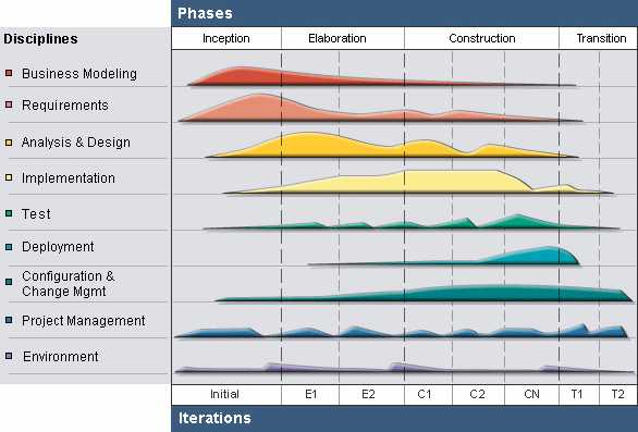
The following image from the IBM Redbook RAD 7
Programmer's Guide summarizes the RUP process.
Phases
& Iterations
"The horizontal axis represents the dynamic structure
and shows the life cycle aspects of a process as time
goes by. It is described in terms of phases and iterations."
Individual Disciplines
The vertical axis represents the static structure and
content respectively. It shows the individual disciplines,
which logically group the process content.
Overview of the Rational
Unified Process
//
image from the IBM Redbook RAD 7 // Programmer's Guide
"RUP divides the life cycle of a project in one or more
individual cycles that focus on the generation of
successive releases of a system (for example, version 1.0
and version 1.1). "
Each cycle consists of four successive phases:
Life Cycle Four Phases
- Inception
- Elaboration
- Construction
- Transition.
Project Milestones
Each of these phases has a special meaning and
concludes with a well defined project milestone.
A phase itself further breaks down in several
individual iterations, each producing some kind
of working software.
Static Content
The static content of the process describes the
'individual artifacts' to be produced:
1. the artifacts themselves
- their characteristics
-standards they will conform to
2. the different roles
- including required skills
- responsibilities within a project
- tasks providing step-by-step explanations
on how specific development goals are to be achieved.
"Related tasks and responsibilities are grouped together
and categorized by disciplines. . . Every discipline defines
a standard way or workflow
of doing the work it categorizes."
Beyond supplying a process framework to structure a
software development process, RUP provides the
following:
- Guidelines
for all team members
- at all portions of the software life cycle.
- both high and low levels
- published in HTML
- Tool mentors,
providing added guidance
- for all development tools , on platform
- Templates and
examples
- for all major process artifacts.
"Rational Application Developer facilitates the use
of the Rational Unified Process by the Process Advisor
feature. This feature provides a seamless integration of
a development process within a development tool. It
enables the development team to work with a common
development process that is configured for a practitioner’s
specific environment."
The Process Advisor
It is via the 'Process Advisor' that the guidance, templates
and tool mentors mentioned above are accessed.
The Process Advisor also allows browsing process views
and managing preferences from within the developer's own
IDE.
To Use the Process Advisor
- select it during installation
- update via the IBM Installation Manager
The Process Advisor consists of the four elements:
//
see accompanying pdf screenshots
Process Advisor Components
- IBM Rational Process Browser
- displays full process contents
- default views are
- Process Advisor itself
- summary list of all sub-process
- represented in UML diagrams
- Process preferences
- select different process configurations or
- set content filtering options for dynamic searches
UML in RAD 7
RAD 7 provides UML visual editing support. This is a
form of visual build tool that simplifies the development
of complex applications.
The tool allows creation and modification of Java classes
and interfaces visually, using Class diagrams. The structure
of an application can be viewed in terms of the relationships
between various Java elements. Changes can be made
without having to flip between the model and code.
//
"Unlike the diagrams offered in Rational Software Modeler
// or Rational Software Architect,
these are visualizations only
// of actual code. Any changes to the
diagrams directly affect the
// underlying code. So, true UML 2.1
modelling is not possible
// using Rational Application
Developer. The UML 2.1 notation
// is used in these diagrams as a way
to visualize and understand
// the code."
Visual Editing
Visual editing allows the development to proceed without
explicitly typing code into a text editor. Components, such
as Java classes are dragged and dropped from a palette
onto a diagram. Further editing can proceed by adding
methods and attributes or defining relations between them.
RAD 7 offers the following types of UML visual diagrams:
RAD 7 UML Visual Diagrams
- Class diagrams
- show some or all application elements
- visually represent and develop
- structures & relationships
- for Java classes and interfaces
- develop Java elements directly from class diagrams
- Browse
diagrams
- temporary diagrams to explore application
- detail, elements and relationships.
- specify a context element to view
- can be converted to
- a UML class diagram or
- save it in an image file
- Topic diagrams
- non-editable
- a quick show of existing relationships
- made by querying the current application state
- queries can be customized
- open multiple copies
- Sequence
diagrams
- show object interactions
- focused on sequence
- timing of message exchange
- Static method
sequence diagrams
- non-editable
- explore the chronological sequence
- of messages between Java instances
- more detailed method interplay
The tools are not Java specific and can work with
XML in creating Web Services.
// see pdf for diagram of a typical
work space setup
Unified Modeling Language
RUP is largely based on models.
"A model - is a
description of a system from a particular
perspective, omitting irrelevant details so that the
characteristics of interest are seen more clearly."
Models are useful for
- understanding problems
- communicating with interested parties
- preparing documentation
- designing applications
Modeling promotes
- better understanding of requirements
- cleaner designs
- more maintainable applications.
UML is a standardized language for modelling different
aspects of an application.
UML can be used to:
- visualize
- specify
- construct
- document the artifacts of an application.
//
a UML favorite word, 'artifact' -'anything made
// by human work or art' - webster's dictionary
The language uses three kinds of building blocks:
- Things
- Relationships
- Diagrams
Things
Things are the basic elements of a model.
The UML defines four kinds of things:
- Structural
things // static elements
- the nouns of a model
- interfaces
- classes
- components
- uses cases
- Behavioral
things //
dynamic parts
- the verbs of the model
- messages exchanged between objects
- Grouping
things
- used to organize a model.
- group semantically related things together
- to a certain context.
- The only UML defined grouping thing
- Annotational
things
- further explanations
- comments in the UML
Relationships
UML defines five kinds of relationships describing
how element are related:
- Dependency
- a semantic relationship where a change
- to one class might affect another class.
- example
- a Bank class depends on an Account class
- because it is used as parameter for an operation.
- Association
- a structural relationship
- describes a connection between objects
- maps to class member declaration
- For example
- a Customer class with a single association
- to an Account class, each Account instance
- is owned by one Customer instance.
- The extends
relationship
- one thing is a specialization of another more general thing.
- maps to the 'extends' keyword in Java.
- For example
- SavingsAccount extends an Account class
- The
implements relationship
- maps to the implements keyword in Java.
- a class that 'realizes' operations defined by an interface.
- The owned
element association
- classes that are owned by a package.
- //
a construct for implementation reasons
- and for hiding information
Diagrams
"A diagram -is a graphical presentation of a set of
elements, most often rendered as a connected graph
of things and their relationships."
UML provides thirteen types of diagrams allowing
capturing, communicating and documenting all aspects
of an application in a standard graphical notation.
The diagrams are categorized into three groups:
- Structural
diagrams
- show the building blocks of an application
- characteristics that do not change over time
- objects, attributes, operations, and relationships.
- Examples
- component diagrams
- class diagrams and
- deployment diagrams.
- Dynamic
behavior diagrams
- how applications responds to requests
- or otherwise evolves over time
- by showing collaborations among objects
- and changes to the internal states of objects.
- Examples
- use case diagrams and
- activity diagrams.
- Interaction
diagrams
- a subset of behavior diagrams
- focused on the exchange of messages
- within a collaboration
- // a
group of cooperating objects
- Examples