The plotter I built way back in high school
It all started 1986 with these stepper motors and interface that my older brother Markus built, and left with me after coming home on a Christmas break from university back in 1986. He even suggested I build a plotter, although I was very skeptical of the idea at first.
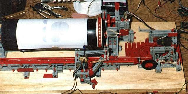
Plotter - in its first practical incarnation
The first 'hardware rev'
During the exam period in the winter, I found myself very bored, and I started tinkering around a bit. I had this cardboard drum which contained V.O. vodka that I got from god knows where, and kept for reasons only a pack rat can understand. This drum was the start of the drum plotter. Drilling a hole in the metal cover on one end, and making a wooden center for the other end provided the basic drum bearings. A Fischer-technik drive chain wrapped around one end, and attached to a sprocket on a stepper motor provided 'vertical' movement. Another chain moved a 'carriage' which had the pen on it. The pen actuation mechanism was pretty much the one I had used in my 'printer' earlier. It consisted of the easiest rolling ball point pen I could find at home (an ordinary BIC pen, ironically). took the 'lead' or cartridge out of it, and screwed the back of it into a the thread of a steel spacer, which fit exactly inside a solenoid from a slide projector. The pull from the solenoid pushed the pen forward, causing it to draw a line when dragged across the paper.
The software
I then started to write software to drive the motors trough the C64's user port. To get the step timing accurately enough, I had to use assembly language to generate the pulses. I ran the assembly language off an interrupt, which I had going off at my 'step rate'. Main line code, which was a mix of assembly language and BASIC, filled a buffer with step instructions, while the assembly language read it out in the background. The slowness of the BASIC components thus were non critical, as plotting was able to continue as BASIC was doing other things. In the process, I learned a principle which is rarely violated on projects though: The software always takes way more effort to develop than the hardware.

Some graphical plotter output
One of the key components was the 'straight line drawing code'. This sounds simple, but really isn't that simple. I had a magazine article from the 'transactor' magazine explaining how to do it, but I couldn't understand it. Besides, the algorithm was targeted at pixels, not line segments. So, not understanding that article, I designed my own from scratch. Reading the article afterwards, I was able to make sense of it then, although I felt that where they differed, mine was better.
Early plotter output
Practical applications
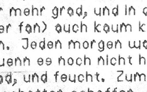
Back in early 1987, after I built the plotter, e-mail was not at all wide spread. Markus and I exchanged a lot of paper letters, and I always printed mine at school, because I didn't have my own printer. Having built a plotter, I now had my very own means of producing paper output.Note that the above output is proportionally spaced. The 'word processor', I used, which was 'Paperclip 64', did not support proportional spacing. But the font that I designed (using a font editor I wrote for the purpose) was proportionally spaced. So I wrote my own text formatter which could read paperclip files, do the printer formatting. Paperlip was not a WYSIWIG sort of word processor, so parsing its files was very straightforward. The tools were very limited back then, but so were the objectives.
The above output is very messy, as it was with an early version of the mechanism, and I was running the plotter at 5 characters per second. Yes, 5 characters! That's pretty fast for any plotter, although real plotters at least write neatly.
Optimizations...
I optimized the mechanism more and more as I went on. I put in more reduction gearing between the motors and the pen movement. I also got rid of the plastic chains as a final drive as the elasticity of the plastic was causing problems. In the first photo on this page, the plastic chain to pull the carriage had already been replaced with a very stiff but light string. I also eventually eliminated most of the Fischer technik of the mechanism in the 'carriage' by making a much lighter and stiffer one out of wood. In the new carriage, the pulls string was attached directly to the pen, to avoid lag from momentum as much as possible.I also optimized the pen up/down mechanism. My drum was not perfectly cylindrical, and it deviated as much as 3mm in radius as a function of x and y. This meant I had to keep the pen a fair distance from it, and then it would hit the paper with too much momentum when the solenoid was powered up. This would then cause the pen to bounce a bit as it hit the paper, and that could be seen in the output. I improved the mechanism by adding a 'feeler' next to the pen. The 'feeler' essentially pushed the pen forward to within 0.5 mm of the paper at all positions on the drum. It was a clever mechanism.
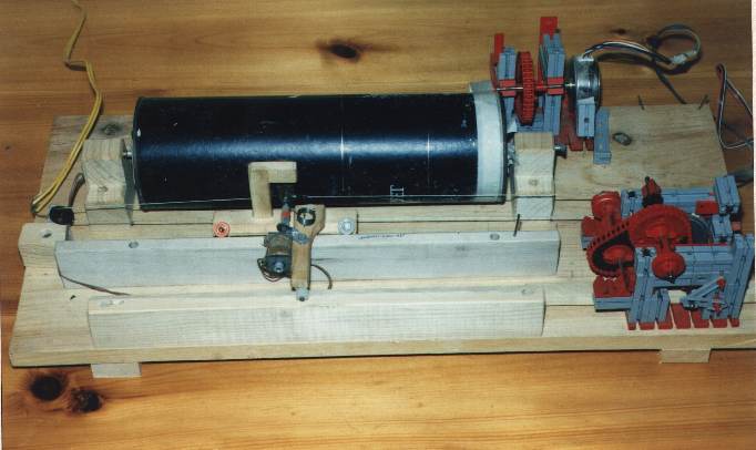
The plotter in its final form
In its glory, the plotter could write at 10 characters per second, in a font that was about 1.5 mm tall, but barely legible! I was constantly pushing the edge, and often having breakdowns.
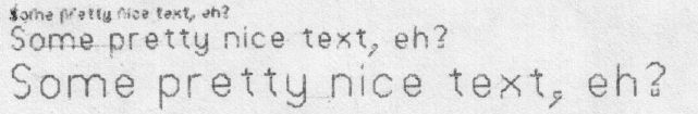
Different text sizes
Late plotter output, maximum speed
My regular size font also became more legible, even at 5 characters per second. I never did optimize out some of the resonance the font caused with the newer mechanism at the highest speed. The above sample is digitized from a letter, where I cared more about speed than print quality. Fact is, it took as long to print the letter as it took to write it!
Doing this sort of hack in Northern Ontario did have its downside though. For one thing, If I didn't have the part, I just plain didn't have it. If it wasn't in my junk inventory, then maybe Radio Shack had it, but that always cost lots of money, and I had to wait until the next time my mom drove to Sault Ste Marie, which was about 80 km away.
On optimizing the electronic drivers, I used a 68 ohm series resistor in series with each stepper coil, Unfortunately, I didn't have 68 ohm power resistors. Despite a cooling fan, I soon burned out all my half watt 68 ohm resistors. The 1/4 watt resistors from radio shack had a tendency to burn out at the multi watt loads I was driving them with, I ganged them up in fours, and the cooling fan in front of the resistors, I was able to drive several watts in to the 1/4 watt resistors. I also had a cooling fan to keep the solenoid cool, as it was not designed for the duty cycles I was using it with.
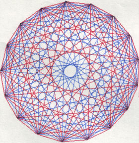
A rare bit of multi colour output. Swapping pens was very difficult
One of the science teachers, Mr Barret, however, did have appreciation for this sort of stuff, and knew it wasn't easy. I told him him everything about it. I was so glad to find an appreciative and understanding soul to tell about this cool hack of mine.
Other related pages on my website: