Building a scanning camera from a flatbed scanner
I'm just itching to buy a really good digital camera, but until they become cheap enough for me to just buy one as a toy, I wanted something digital camera like to play with.
I started playing around with my flatbed scanner to see if I could capture images of stuff around it, by holding the scanner in my hand and rotating it as it scanned. This allowed the focusing lens in the scanner to pick up some of the light from the surroundings. One of my first experiments looked like this:
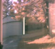
My very first attempt at photography with a flatbed scanner
It took a bit of tweaking with the colour balance to get the colours to look even this close to real. Focus was of course way off, as the lens was focused on the glass plate.
This looked moderately promising. I know people are hypothesizing about using a lens to focus an image onto the bed of a flat bed scanner, so that the scanner can pick up the image at the focal plane. I don't think this could work very well though, s as it would require a toroidal condenser, or ground glass to diffuse the light at the focusing plane, and that would waste most of the light.
Camera mechanism
My approach basically involves trashing a $100 scanner. I disassembled the scanner and took out all the electronics, the CCD image sensor, and the stepper motor mechanism, and built a new mechanism to hold it all together, and rotate the CCD and lens assembly to scan its environment, instead of a piece of paper.
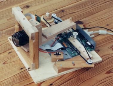
Front view of my scanning camera
For the lens, I used an obsolete 35mm F/2.8 screw mount SLR camera lens. The lens is so obsolete, its even predates the Pentax screw mount (which I still use). The lens has no anti reflective coating, and, a completely manual aperture - that is, it even predates the automatic aperture reduction when the shutter is released. Its entirely manual. Perfect for the job.
I mounted it to the CCD by cutting a slot in a block of wood. On the back side, I mounted the scanner's PCB with the linear CCD. On the front side, I mounted a lens cap (with a hole cut in it) to the wood, and screwed the lens into that. Surprisingly, from my rough calculations, I got the lens within .002" of the right distance from the CCD for the focusing scale to be correct. Careful sanding corrected the rest of the error.
The lens and CCD assembly is rotated on two metal points, which poke into small holes in the the wooden frame from the top and bottom. The points are just the tips of screws, which are of course easily adjusted.
This method of scanning does cause the perspective to be more 'cylindrical' than rectilinear, but for most shots, it's either not noticeable, or not bothersome. To get rectilinear perspective, I would have to move the CCD in a straight path while leaving the lens fixed in position, and that wouldn't be easy to do with simple means.
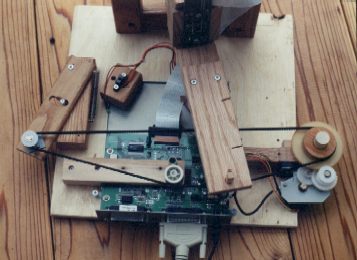
The mechanism for rotating the lens turret
My original idea was to have an elaborate gearing mechanism to rotate the turret, but going through my collection of miscellaneous gears, I just couldn't find the right kind of mating gears to make this work. That, and to preserve a reasonable aspect ratio with a 35 mm focal length lens, I couldn't rotate it through more than 60 degrees in one scan anyway. As such, using the toothed belt from the scanner to pull an arm at the back of the turret was a more logical choice.
Because I used all the electronics from the scanner unaltered (except for removing the illumination light), I could just use the software that came with the scanner straight to operate it. This software is not quite optimized for the task, but I wasn't about to spend a hundred hours reverse engineering it and writing new driver software. Mind you, doing that sort of thing shouldn't be impossible. It turns out that this cheap scanner (like many others) has absolutely no smarts built in. It's all bit-bashed through the printer port, and the PC even has to generate the steps for returning the scan head to home position! So basically, all the software to operate it sits on the PC. (So instead of efficient embedded code, the driver is probably some badly designed piece of object oriented bloatware).
Colour convergence and aspect ratios
The rate of rotation per stepper motor step turned out to be very important. For black and white, the error can be corrected by stretching the resultant image. But for coluour photos, the colour convergence is all wrong if the image does not move across the CCD as a function of stepper steps as the software expects it to. This is because the CCD has three separate sensor strips for red, green, and blue side by side. The software takes the readings for each colur from different scan positions and combines them to converge the colour correctly. If the image doesn't move across the CCD at the right rate, this compensation is inaccurate.
Another thing I discovered was that, in order to get colour convergence to work, I needed to set it up to produce a mirror image. This was because the beam folder in the original scanner had an odd number of reflections, thus resulting in a mirror image hitting the CCD. In order to keep the software happy, I just set it up so that the lens rotated in the opposite direction that it used to scan. It always gives me a mirror image, but this is easy to fix in the photo editor.
For rotating the turret, I first just ran the scanner's belt directly over the gears as it had done in the scanner, and have the belt pull the back of the turret around. However, this produced more rotation per step than appropriate. Because of space constraints and limited belt length, I couldn't make the arm much longer to reduce the angle either. So, going to my box of miscellaneous gears again, I found a gear that mated fairly well with the toothed pulley for the belt already on the gear assembly. This effectively gave me another gear of reduction. To get the rate of rotation exactly right, I computed the ratio I needed by checking the distortion on circular objects I scanned, and then made a pulley to the exact diameter on my lathe. Around this pulley, I ran the belt. The drive is entirely friction based, but because the belt only rotates a turret on two points, slippage has not been a problem.
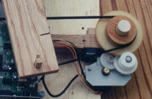
Scanner gear reduction plus one extra gear I added
On the other end of the belt, I put a tensioned idler, using, of course, the original idler pulley from the scanner. I also put an idler in the middle of the belt. This makes the back of the belt loop approximate an arc more closely, and gives a rate of turret rotation per stepper rotation more consistent over its entire range. If you don't understand why, don't worry - most people don't.
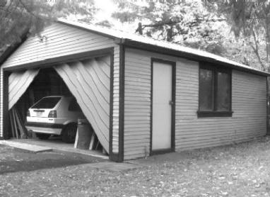
A picture I took of the garage while the door was moving
This digital scanning camera is of course only as fast as the original scanner was, which is to say not very fast. I opened and closed the garage door while I took the shot above. Really makes it look like there's something gone very wrong with the garage door. I have had that garage door jam and derail before, but never as bad as it looks in this photo!

A super close up - using extension tubes behind the lens
I took this photo by mounting some extension tubes behind the lens for a real close up. The resolution on the actual object is over 1000 DPI! The shot took forever to set up, but once set up, its easy to take pictures of different things (it's tweaky much like it's tweaky to get the 'perfect' print in a darkroom)
Colour balance and CCD problems
The CCD and software is of course designed to operate in a scanner, which has fixed exposure and lighting. In the scanner, the subject is always passively lighted with the same florescent tube. In real life, things are less consistent. It turned out that the CCD is not very well set up for dealing with very bright spots in the image, and if a bright spot is encountered, a streak is pulled across the image. Exactly why I don't know, but either the A/D converter or the CCD get screwed up when a very strong signal is scanned out of it.
A streaking artifact caused by a reflective spot
Another problem is that the CCD's colour balance is set up to work with a cool white fluorescent bulb. When the subject is lit with a cool white fluorescent bulb, the colours come out quite realistic. Daylight tends to be overly red, and daylight balanced fluorescent don't have enough blue. Incandescent illumination is pretty much unusable for colur photography. This is because the CCD is very infrared sensitive, and there is no anti-IR filter in the optical path. So the red CCD also picks up all the infrared light, and no amount of playing with the colour balance will make the result look colour realistic. Black and white photography with incandescent illumination works pretty well, although the CCD is picking up more infrared than visible light. Anything made of black anodized aluminum, for example, shows up as light gray instead of black. Some dark thin fabrics you can see through a bit, so there is a bit of truth to this story of seeing through clothing with infrared camcorders.
On the whole though, with enough tweaking, it is possible to get some very sharp images over 2000x2000 pixels in size.
More pictures taken with the scanner
Most of the photos on my Lego Machines page were also taken with the scanner.
Update:
Well, within a year of building this contraption, I bought a digital camera always. My first digital camera was an Olympus D340R. My third digital camera, a 4 megapixel Canon S40 could finally do better than the scanner. Really, haven't used the scanning camera contraption at all since I got a real digital camera. Its too much effort to set up, so its not a practical alternative to a regular digital camera. Most of the photos on my Lego Machines page were also taken with the scanner.Other people have had the idea of scanning real life with a scanner too:
-
Demonstration Quality Scanning Digital Camera.
By a professor at RIT. Must be nice to get paid to hack around like that!
Panorama scanning camera from a scanner. Very elaborate description, and quite recent. Picture quality is not so good.
Other photo related pages on my website: